Read the OCR text
New
ONE of the most important
news items for motor
racing enthusiasts in New
bealand and Australia in
recent months has been the
announcement of a new
racing engine designed
specifically with the Tasman
formula in mind. The
formula will continue as al
present until 1968 at least.
No drivers will be using
the new engine this season,
but it is almost certain lo
be in wide use next season.
If it is successful, as is
hoped it may, by next season, have replaced the successful and long-lived
Coventry Climax fourcylinder engine almost
completely.
This Tasman series may
he the swan-song of the
robust Coventry Climax.
Repco late last year announced the most important
development yet in its
Repeo-Brabham racing programme: complete Repco V8
raeing engines, fully designed by Repeo engineers and
produced almost entrely in
Repco factories.
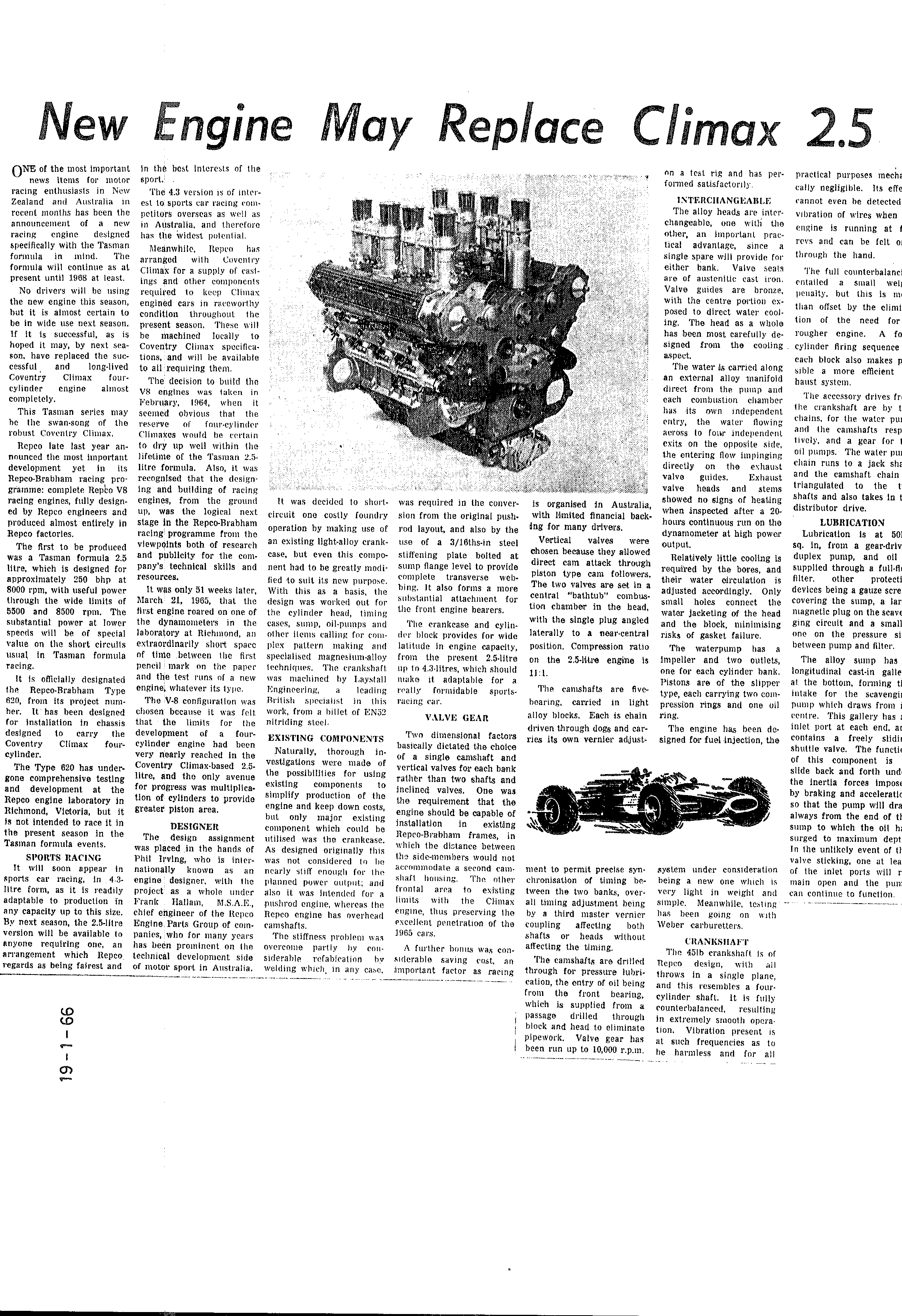
The first to be produced
was a Tasman formula 2.5
litre, which is designed for
approximately 250 bhp at
8000 rpm, with useful power
through the wide limits of
5500 and 8500 rpin. The
substantial power at lower
speeds will be of special
value on the short circults
usual in Tasman formula
racing.
It is officially designated
the Repco-Brabham Type
620, from its project number. It has been designed
for installation in chassis
designed 10 carry the
Coventry Climax four•
cylinder.
The Type 620 has undergone comprehensive testing
and development at the
Repeo engine laboratory in
Richmond, Victoria, but it
is not intended to race it in
the present season in the
Tasman formula events.
SPORTS RACING
It will soon appear in
sports car racing, in 4.3litre form, as it is readily
adaptable to production in
any capacity up to this size.
By next season, the 2.5-litre
version will be available to
anyone requiring one, an
arrangement which Repco
regards as being fairest and
- 66
19-
Engine
May
Replace
Climax
in the best interests of the
sport.
The 4.3 version is of interest lo sports car racing competitors overseas as well as
in Australia, and therefore
has the widest potential.
Meanwhile, Repen has
arranged with Coventry
Climax for a supply of castings and other components
required to keep Climax
engined cars in raceworthy
condition throughout the
present season. These will
be machined locally to
Coventry Climax specifications, and will be available
to all requiring them.
The decision to build the
V8 engines was taken in
february, 1964, when it
seemed obvious that the
reserve four-eylinder
Climaxes would be certain
to dry up well within the
lifeline of the Tasman 25litre formula. Also, it was
recognised that the designing and bullding of racing
engines, from the ground
up, was the logical next
stage in the Repco-Brabham
racing programme from the
viewpoints both of research
and publicity for the conpany's technical skills and
resources.
It was only 51 weeks later,
March 21, 1965, that the
first engine roared on one of
the dynamometers in the
laboratory at Richmond, an
extraordinarily short space
nf time between the first
pencil mark on the paper
and the test runs of a new
engine, whatever its typc.
The V-8 configurallon was
chosen because it was felt
that the limits for the
development of a fourcylinder engine had been
very nearly reached in the
Coventry Climax-based 2.5litre, and the only avenue
for progress was multiplication of cylinders to provide
greater piston area.
DESIGNER
The design assignment
was placed in the hands of
Phil Irving, who is internationally known as an
engine designer, with the
project as a whole under
Frank: Hallam, M.S.A.E.,
chief engineer of the Repco
Engine Parts Group of companies, who for many years
has been prominent on the
technical development side
of motor sport in Australia.
38*
on a test rig and has pel
formed satisfactorily.
INTERCHANGEABLE
The alloy heads are interchangeable, one with the
other, an important practical advantage, since a
single spare will provide for
either bank. Valve seats
are of austenitic cast iron.
Valve guides are bronze,
with the centre portion exposed to direct water cooling. The head as a whole
has been most carefully designed from the cooling
aspect.
The water is carried along
an external alloy manifoid
direct from the pump and
each combustion chamber
has its own independent
entry, the water flowing
across to four independent
exits on the opposite side,
the entering flow impinging
directly on the exhaust
valve guides. Exhaust
valve heads and stems
It was decided to short-
circuit one costly foundry
operation by making use of
an existing light-alloy crankcase, but even this component had to be greatly modified to suit its new purpose.
With this as a basis, the
design was worked out for
the cylinder head, timing
cases, sump, oil-punps and
other ilents calling for complex pallern making and
specialised magnesium-alloy
lechniques. The crankshaft:
was machined by Daystall
Engineering, leading
British specialist in this
work, from a billet of EN52
nitriding steel.
EXISTING COMPONENTS
Naturally, thorough investigations were made of
the possibilities for using
existing components to
simplify production of the
engine and keep down costs,
but only major existing
component which could be
utilised was the crankcase.
As designed originally this
was not considered to be
nearly stiff enough for the
planned power output; and
also it was intended for a
pushrod engine, whereas the
Repeo engine has overhead
camshafts.
The stiffness problem was
overcome partly by considerable refabication by
welding which, in any case,
was required in the conver-
sion from the original pushrod layout, and also by the
use of a 3/1ßths-in steel
Stiffening plate bolted at
sump flange level to provide
complete transverse webhing. It also forms a more
substantial atlachment for
the front engine bearers.
The crankcase and cylinder block provides for wide
latitude in engine capacity,
from the present 2.5 litre
up to 4.3 litres, which should
make it adaptable for a
really formidable sportsracing car.
VALVE GEAR
Two dimensional factors
basically dictated the cholce
of a single camshaft and
vertical valves for each bank
rather than two shafts and
inclined valves. One was
the requirement that the
engine should be capable of
installation in existing
Repeo-Brabham frames, in
which the distance between
the side-members would not
accommodate a second camshafl housing. The other
frontal area to existing
limits with the Climax
engine, thus preserving the
excellent penetration of the
1965 cars.
A futher bonus was consilerable saving cost, an
important factor as racing
is organised in Australia,
with limited financial backing for many drivers.
Vertical valves were
chosen because they allowed
direct cam attack through
piston type cam followers.
The two valves are set in a
central "bathtub" combustion chamber in the bead,
with the single plug angled
laterally to a near-central
position. Compression ratio
on the 2.5-Mue engine is
11:1
The camshafts are fve-
bearing, carried in light
alloy blocks. Each is chain
driven through dogs and carries its own vernier adjust-
showed no signs of heating
when inspected after a 20hours continuous run on the
dynamometer at high power
output.
Relatively little cooling is
required by the bores, and
their water circulation is
adjusted accordingly. Only
smah holes connect the
water jacketing of the head
and the block, minimising
risks of gasket failure.
The waterpump has a
Impeller and two outlets,
one for each cylinder bank.
Pistons are of the slipper
type, each carrying two compression rings and one vil
ring.
The engine has been designed for fuel injection, the
ment to permit precise synchronisation of timing between the two banks, overall timing adjustment being
by a third master vernier
coupling affecting both
shafts or heads without
aflecting the timing.
The camshafts are dritled
through for pressure lubrication, the entry of oil being
from the front bearing,
which is supplied from a
passage drilled through
block and head to eliminate
pipework. Valve gear has
been run up to 10,000 r.p.mn.
system under consideration
being a new one which is
very light in weight and
simple. Meanwhile, testing
has been going on with
Weber carburetters.
CRANKSHAFT
The 45lb crankshaft 1s of
Repeo design, with all
throws in a single plane,
and this resembles a fourcylinder shaft. It is fully
counterbalanced, resulting
in extremely smooth operation. Vibration present is
at such frequencies as to
he harmless and for all
25
practical purposes mech
cally negligible. Its effe
cannot even be detected
vibration of wires when
engine is running at
evs and can be felt o
through the hand
The full counterbalanc
entailed small wei
penaity, but this is m
than ofiset by the elimi
tion of the need for
rougher engine. A fo
cylinder fring sequence
cach block also makes p
sible a more efficient
haust system.
The accessory drives fr
the crankshaft are by t
chains, for the water pu:
and the camshafts resp
lively, and a gear for
oil pumps. The water pu
chain runs to a jack sha
and the camshaft chain
triangulated to the
shafts and also takes In
distributor drive.
LUBRICATION
Lubrication is at 50
sq. in, from a gear-driv
duplex pump, and oll
supplled through a full-fl
filter. other protecti
devices being a gauze scre
covering the sump, a lar
magnetic plug on the scave
ging circuit and a small
one on the pressure si
between pump and filter.
The alloy sump bas
longitudinal cast-in galle
at the bottom, forming t
intake for the scavengi:
pump which draws from
centre. This gallery has
inlet port at each end. a
contains a freely slidi
shuttle valve. The functi
of this component is
slide back and forth und
the inertia forces imposi
by braking and acceleratl
so that the pump will dra
always from the end of tl
sump to which the oll h
surged to maximum dept
In the unlikely event of fl
valve sticking, one at lea
of the inlet ports will r
main open and the pun
can continue to function.
Summaries and tables are machine-read from the scan and may contain errors: the scan is the record.